Create machine templates
Prerequisites
Access to the Settings App
Creation of a machine template
- click on the entry "Machines " in the navigation menu
- click on the entry "Machine template " in the submenu.
- click on the "" button to create a new machine template.
The following dialog box appears:
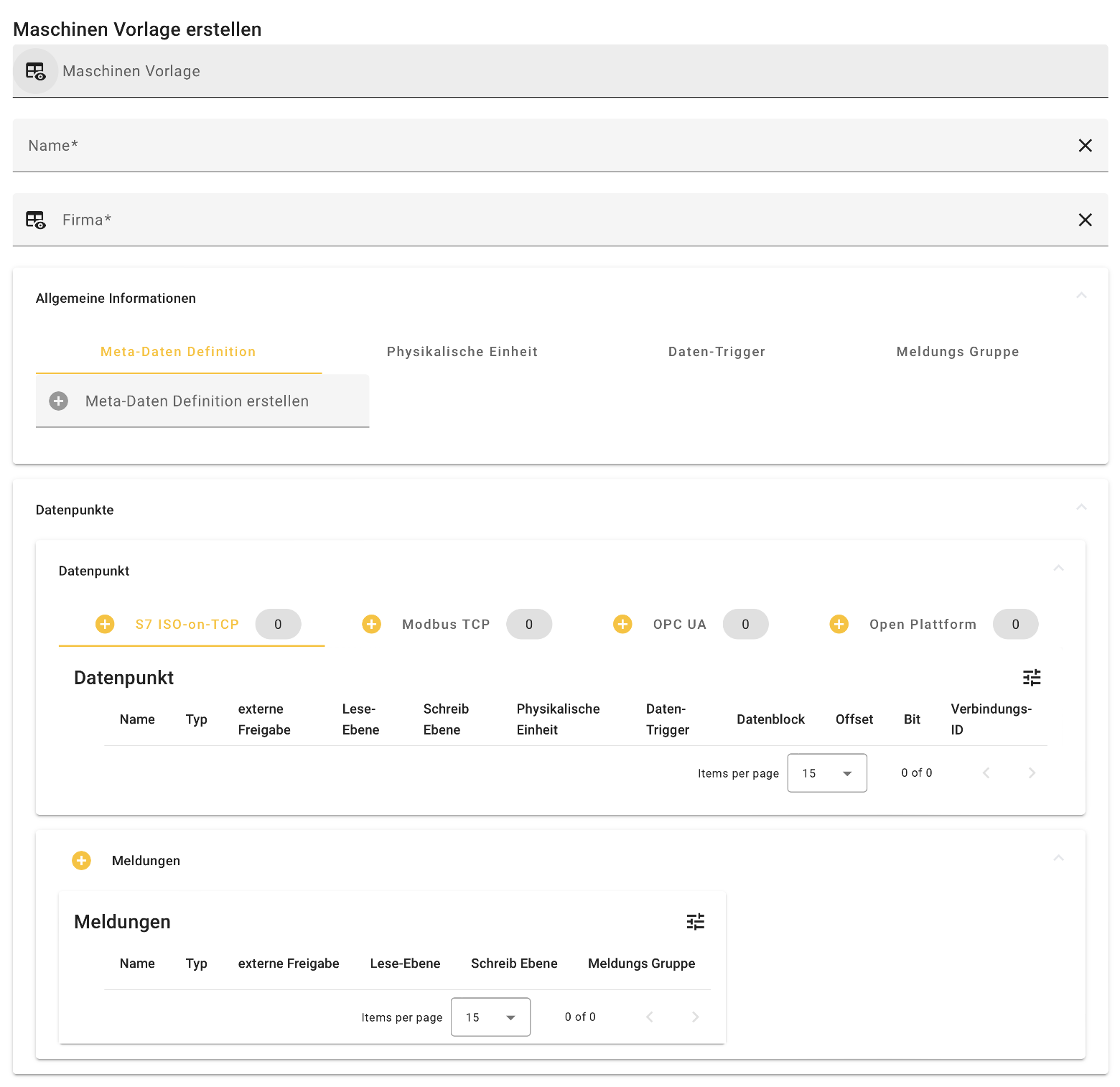
| Field / Tab | Description |
|---|---|
Machine template |
A copy of an existing machine template can be created. |
Name |
Any name can be selected here for the machine template to be created. |
Company |
The company that manages the machine template. |
| General information | Meta data (individual), physical units (e.g. bar), data triggers (e.g. cyclic, 1500ms) and message groups (e.g. warning, prio 1) can be defined here. |
| Data points | The data points to be recorded must be defined. Various interfaces/protocols are supported. |
| Messages | Messages that can be created on the basis of data points and message groups. |
After clicking on "Send", the machine template appears in the Settings app.
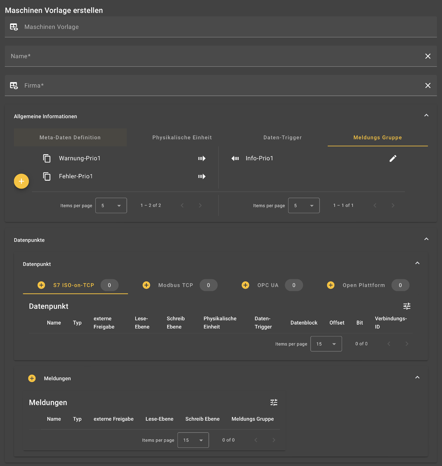
General information
Metadata, physical units, data triggers and message groups can be defined under general information.
Physical units, data triggers and message groups are created in the same way:
By clicking on the button, units/triggers/message groups can be created via a dialog box. After creation, these are displayed on the right-hand side of the respective tab and are thus assigned to the machine template to be created.
Existing entities/triggers/message groups can be assigned to the machine template by clicking on the arrow symbol on the right-hand side. The assigned entities can be edited using the button.
To store additional information for machines (e.g. a project number), you can create corresponding data fields:
- enter the name of the data field in the text field.
- click on to add the field.
- use to remove a field again.
The metadata definitions can be translated into the available languages so that they are displayed in the respective user language.
You can also use the "Show in alerts" slider to specify whether the metadata should appear in notifications.
When you create a new machine from a template, the settings for "Show in alerts" are automatically applied (but can be overwritten).
Physical units are assigned to the machine data to be recorded during the subsequent creation of data points. When creating a physical unit, the 'symbol' of the unit and optionally the 'name' of the unit are defined in different languages.
Data triggers determine the times of data acquisition and are assigned to the machine data to be acquired during the subsequent creation of data points. When creating data triggers, the 'name' of the trigger and the 'trigger type' (e.g. cyclical, on value change) are defined first. Depending on the trigger type, the following information is also specified:
- cyclic:
| Keyword | Description |
|---|---|
| The measured value is written to the database at regular intervals (cycle time in milliseconds). |
- on value change
| Keyword | Description |
|---|---|
Minimum interval |
Minimum interval in which the assigned measured value is written. If the value changes several times in this interval, only the minimum interval is taken into account. |
| If the value does not change for a long time, the value is saved again after the maximum interval. | |
| The deviation when a value change is large enough to be recorded. (Deviation > Delta Change) |
When messages are created, they are each assigned to a message group to enable the messages to be categorized. Message groups contain the following information:
| Keyword | Description |
|---|---|
Name |
Name of the message group |
Priority |
Optionally, messages can be ordered according to their relevance by defining a priority for the message group. |
Message type |
Here you can specify whether the messages in the group are information, warnings or errors. |
Data points
Requirements
Adding data triggers to the machine template
Create data points
The data points of the machine template specify which measurement or control values are recorded for a machine. They can be specified and assigned to a machine template both during the creation and subsequent editing of a machine template.
Data can be recorded using various interfaces (S7 ISO-on-TCP, Modbus TCP, OPC UA, Open Platform). A new data point can be created by clicking on the button in the tab of the respective protocol. General information, value properties, connection details and information on scaling are defined in the corresponding dialog window.
More detailed documentation on creating triggers and data points can be found here.
| keyword | description |
|---|---|
Name |
Name of the data point (can optionally be specified in different languages) |
Type |
Classification of the data point as a measured value or as a control value |
Data trigger |
The data trigger that defines the time of data acquisition for the data point |
Physical unit |
The physical unit of the data point (optional) |
| Keyword | Description |
|---|---|
Local |
not yet used (placeholder for decentralized applications on the Edge.) |
SQL |
Values are recorded historically and regularly written to the SQL database |
Time series |
Values are recorded historically and written regularly to the time series database, depending on the data trigger |
Live value |
Values are not recorded historically, only the last measured value is saved. |
| The end customer determines whether the measured value may be sent from the PLC to the cloud and made available to the higher-level manufacturer (not currently evaluated). |
| Keyword | Description |
|---|---|
Connection type |
Fieldbus protocol of the data acquisition (e.g. S7, Modbus or OPC UA) |
Data type |
The data type (e.g. boolean, string) of the data to be recorded |
S7 data block |
The data block in an S7 PLC. This must not be optimized, i.e. it must be accessible via PUT/GET. |
S7 Offset |
The offset address within the data block |
Modbus address |
The offset address of the register, e.g. 41002 |
Modbus function |
The Modbus function to be used, e.g. FC_1_READ_COIL_STATUS |
OPC UA address |
The address of the variable to be read, e.g. s='Test 123' or i=12 |
OPC UA namespace |
The OPC UA namespace, e.g. ns=3 (only enter the integer value) |
Connection ID |
Default 0; The driver allows multiple connections to be established, i.e. a new connection (e.g. to the PLC) is configured for each ID |
| keyword | description |
|---|---|
Scaling with/without value limitation |
Measured values are limited to the MIN and MAX values of the output side if they are exceeded. In the case of scaling without value limitation, the values actually calculated for MIN and MAX are used. |
| Minimum and maximum values on the input side | Minimum/Maximum input |
Minimum/Maximum Output |
Minimum and Maximum value on the output side |
Offset |
The standard offset that is added to each measured value after scaling before saving. |
| Accuracy` | Number of decimal places to which the output value is rounded during scaling. |
Messages
Requirements
Add message groups to the machine template
Create messages
Messages are used to monitor the measured values of a data point over time and to document a limit value violation or a trend, for example. They can be specified and assigned to a machine template both during the creation and subsequent editing of a machine template.
| Keyword | Description |
|---|---|
Name |
Name of the message (optionally specifiable in different languages) |
message group |
message group to which the message is to be assigned |
Write level |
not yet used |
Read level |
not yet used |
| Keyword | Description |
|---|---|
Local |
not yet used |
SQL |
Values are stored in a SQL table. |
Time series |
Values are recorded historically and written regularly, depending on the data trigger |
Live value |
Values are not recorded historically, only the last measured value is saved. |
Share |
Describes whether the measured value may be sent from the PLC to the cloud. |
Note
It is mandatory that messages have SQL selected
The button can be used to specify new data points and add them to the message. Alternatively, data points that have already been created can be added to the message using the button. The event that triggers a message must be specified for each selected data point: Click here for an overview of all data triggers